Saturday, April 1, 2017

Front Fender Mock-up Part 2

Okay, its been a while since my last post...  I got back to work on the truck today and resolved the modified fender mounting studs from the previous past "Front Fender Mock-up Part 1."  The problem was resolved by cutting them off and drilling out pilot holes where the factory holes should have been on the cab.  It took lots of internet searching to find other projects with good photos of the cabs when disassembled to convince me that this was the right thing to do since the factory holes did not look like they were in the same places as the welded studs.

Offending studs on passenger side:
  Cut off with the saws-all and ground down flush:

Fender installed with three bolts to check the fit:
 Another angle:
 Passenger side studs and cancerous devastation:
 Studs cut off and ground down flush:
 You can see the new holes drilled in the cab offset from the stud locations.  Scary...
 Drivers' side fender installed with three bolts to check the fit:
 Its starting to look like a truck again!


Monday, February 6, 2017

New Power Relay

I knew it wouldn't last forever.  The truck is wired with a remote power/accessory solenoid relay as explained in a previous post and it burned out.  Not surprising because it is actually a factory starter solenoid, which is undoubtedly rated for intermittent duty.  I have replaced it with a 200 amp continuous duty Cole Hersee solenoid that is more appropriate for this application.

Original solenoid:
 Stripped down:
 New solenoid:
 Installed and wired.  There is an extra black cable on the left post that I put there out of convenience for the time being.  It will eventually be connected to the battery.

Tuesday, January 3, 2017

Front Fender Mock-Up Part 1

In order to bolt down the radiator support bracket and move on with the engine work, I have to get it aligned on the frame so that the fenders and hood will bolt up correctly with even joint/seam spacing.  This is all necessary because the original tilt front clip installed on the truck had a non-factory radiator mount and the holes for the factory configuration were apparently never drilled int he frame.

I have the central bolts installed hand tight to allow movement and adjustment.  The missing frame holes in question can be seen on either side of the two central bolts.
 Everything hung on the radiator mounting bracket hand tight.  This part went quickly and was relatively painless.
 Another angle.
 Front the back.
 I have three of these gravel pans.  One steel one is bent and warped on the driver's side, the fiberglass one is crushed and broken on the passenger side, and the beautiful black steel one is made for trucks without the frame rail protrusions to delete the front bumper.  In short, I do not have a good straight gravel pan to put on the truck for alignment purposes...  :o(
I chose to install the broken fiberglass one as it was less bad than the bent steel one.
 Bumper resting on frame.  Not required for this, but I thought it would look good with the rest of the panels installed.
 Another angle.
This gap between the radiator and gravel pan does not look very good to the eye.  I'll do some research to see if this is normally present or not.  It might be an illusion because to the front grille is not yet installed.
 Another view of the radiator gap.
I attempted to fit the passenger side fender onto the cab studs, but it would not mate. 
 So, I cleaned the paint and bondo off the studs with a wire wheel and tried again.  Before:
 After:
 It turns out that the fenders have threaded nuts welded inside the mounting holes, which indicates they were designed to interface with a bolt, not a fixed stud. 
Well, its off to consult the internet on the bolt/stud situation and the case of the maybe-too-large radiator gap...

Monday, January 2, 2017

Gentlemen, Start Your Engines!

She fired right up after the fuel reached the carburetor through the dry and empty line.


Now that the engine is semi-functional, I'll need to finish the wiring for the new electric radiator fan and secure the radiator mount to the frame.  I'll let it warm up and check the timing after everything is working and full of coolant.


New Ignition Circuit

The new main power switch and the ignition switch were mounted today along with the installation of a new fuse box and ignition circuit.  The existing circuit was not ideal for the future vision of the truck, so it was worth the extra time to run a new switched lead to the ignition coil.

Got some input from the spouse on where the buttons should go:
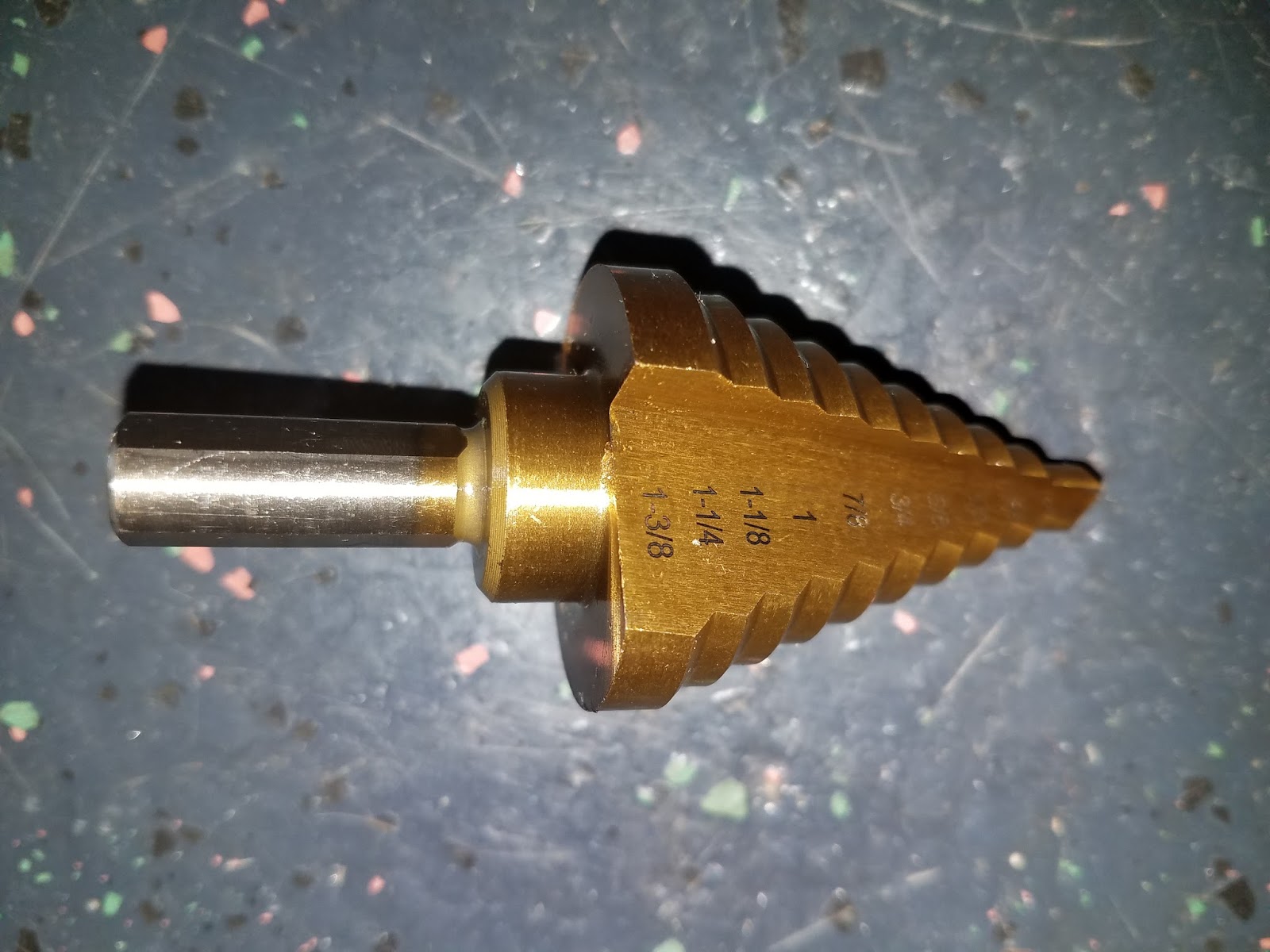
 I purchased a new stepped drill bit from Amazon for $8 since the ones at the hardware store were $39.  These things are pretty cool and allow you to drill progressively larger sheet metal holes the deeper you push the bit.  They are mainly used to drill taps into electrical service boxes.
 Getting it done.
 Bam!  The left one is the main power switch, which lights up when the power is on like most common electronics.  The one on the right is the momentary starter switch and it lights up blue only when you press the button. 
For reference, here are some pictures of the existing fuse panel.  It is on the driver's side above the new clutch pedal assembly.  As you can see, it is in the same condition as the rest of the truck and even has more bonus pecan shells...
 
 
 Here are the supplies for the new ignition circuit.  8 AWG stranded wire, some end connections, and a marine fuse panel.


 I hung the box temporarily from an existing screw hole under the dash on the passenger side just to see what it looked like and to take some rough measurements.
 I cut and terminated some wires for the new circuit.

 After deciding that the spot looked good, I mounted the box to the firewall and made the first connections for the ignition circuit.  This box will eventually have connections for all of the interior accessory branch circuits.
 With the cover installed.
The truck has this bank of toggle switches on the left side of the steering wheel.  I assume that they are supposed to control the electric power windows that are in the original doors and other random things like the interior dome light.  I don't know for sure because none of those things work and I haven't invested any time in tracing all of the lines down.  For now, I am going to commandeer one of the slots for the new ignition switch so I don't have to drill another hole in the dash.  I might eventually move the switch to another spot that looks better, but we'll cross that bridge when we get there.
 Taking out the old switch.
 The new switch is an illuminated ON/OFF toggle with a blue cover.
 Testing out the switch and light.  It has a blue LED like the round power and starter switches.
 Installed and ready to go!
I used a spark plug ignition tester to make sure the ignition system was actually firing the plugs.  These things duplicate the spark plug configuration outside of the engine so you can see the spark when you crank the engine and visually verify it is working.  You can also remove a spark plug from the engine and do the same thing by grounding the plug body, but using the tool lets you do it hands-free so you can take a picture for your blog.
 Clamped onto a ground and ready to fire.  I used child labor to sit in the cab of the truck and push the starter button as I watched.  It fired as it should, so we are good to go from an ignition standpoint.

Thursday, December 29, 2016

Electrical Wiring Modifications

So, the new steering column is installed and we are on our way.  The old column had an integral key ignition switch, but the new one does not.  This is okay for two reasons: 1) Mounting the switch on the dash is going to look cooler, and 2) the dash mounted switch fits better into the long term plan for the all-electric conversion down the road.

First, the new high torque modern starter motor is capable of switching the full current load when starting unlike old OEM starters, so you can wire them up differently without a starter relay.  This enables me to re-purpose the original starter relay as a master power relay for the whole vehicle.  To do this, I basically moved all of the load side wire connections to the opposite side of the relay from the battery lead.  Configured this way, the truck will be completely dead until the "master switch" is activated on the dash, then power will be available to everything on the vehicle.  The new master switch itself is rated for ~5 amps, which would burn up under the load experienced by the relay.

 To find the correct wire lead under the dash that originally served as the starter switch signal, I made a short hot wire that I could clip to the battery.

 The starter relay activated with a distinctive "thud" when I hit the right pin with the 12V hot wire.
 The new master power switch wiring is pretty straightforward.
 
Here it is!  The new power switch has a modern styling and lights up with a blue LED when activated.  Thinking ahead, this switch will be coupled with a push button starter switch and a RFID key fob just like a modern vehicle.  No old fashioned key on this hot rod...  Just get in the truck, push the start button, and away you go!