The new main power switch and the ignition switch were mounted today along with the installation of a new fuse box and ignition circuit. The existing circuit was not ideal for the future vision of the truck, so it was worth the extra time to run a new switched lead to the ignition coil.
Got some input from the spouse on where the buttons should go:
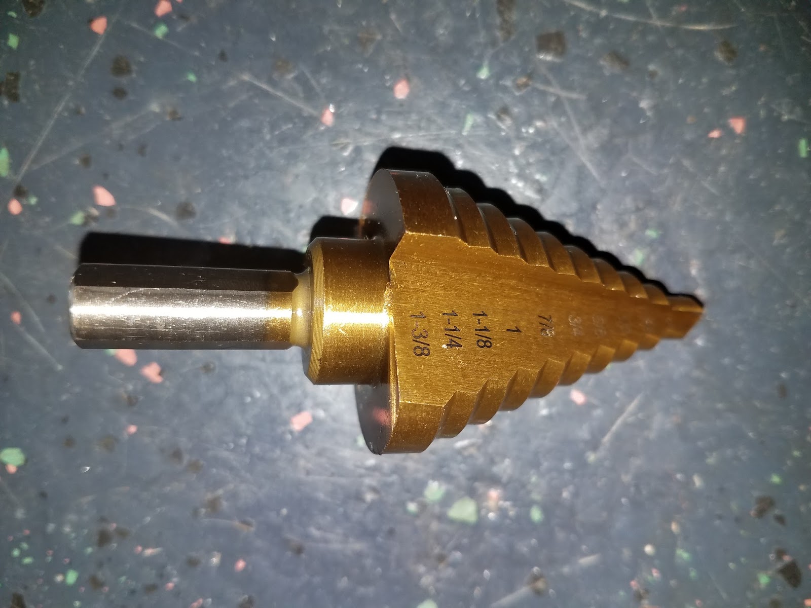
I purchased a new stepped drill bit from Amazon for $8 since the ones at the hardware store were $39. These things are pretty cool and allow you to drill progressively larger sheet metal holes the deeper you push the bit. They are mainly used to drill taps into electrical service boxes.
Getting it done.
Bam! The left one is the main power switch, which lights up when the power is on like most common electronics. The one on the right is the momentary starter switch and it lights up blue only when you press the button.
For reference, here are some pictures of the existing fuse panel. It is on the driver's side above the new clutch pedal assembly. As you can see, it is in the same condition as the rest of the truck and even has more bonus pecan shells...
Here are the supplies for the new ignition circuit. 8 AWG stranded wire, some end connections, and a marine fuse panel.
I hung the box temporarily from an existing screw hole under the dash on the passenger side just to see what it looked like and to take some rough measurements.
I cut and terminated some wires for the new circuit.
After deciding that the spot looked good, I mounted the box to the firewall and made the first connections for the ignition circuit. This box will eventually have connections for all of the interior accessory branch circuits.
With the cover installed.
The truck has this bank of toggle switches on the left side of the steering wheel. I assume that they are supposed to control the electric power windows that are in the original doors and other random things like the interior dome light. I don't know for sure because none of those things work and I haven't invested any time in tracing all of the lines down. For now, I am going to commandeer one of the slots for the new ignition switch so I don't have to drill another hole in the dash. I might eventually move the switch to another spot that looks better, but we'll cross that bridge when we get there.
Taking out the old switch.
The new switch is an illuminated ON/OFF toggle with a blue cover.
Testing out the switch and light. It has a blue LED like the round power and starter switches.
Installed and ready to go!
I used a spark plug ignition tester to make sure the ignition system was actually firing the plugs. These things duplicate the spark plug configuration outside of the engine so you can see the spark when you crank the engine and visually verify it is working. You can also remove a spark plug from the engine and do the same thing by grounding the plug body, but using the tool lets you do it hands-free so you can take a picture for your blog.
Clamped onto a ground and ready to fire. I used child labor to sit in the cab of the truck and push the starter button as I watched. It fired as it should, so we are good to go from an ignition standpoint.